What is a Rectifier Circuit?Since we've ventured down the AC voltages to a level that is more in accordance with the voltage prerequisites of the $\mu$Stamp11, we are left with the issue of changing over a 12 volt AC signal into our ideal 5 volt DC control supply. We'll move toward this in two stages. First we'll change over the AC voltage into a DC voltage by means of a procedure known as correction. At that point we'll step down this 12 volt DC voltage down to 5 volts utilizing the voltage controller . This area quickly discusses the correction procedure.
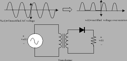
The least complex conceivable circuit for changing over AC into DC is a half-wave rectifier. This circuit comprises of a solitary diode that just enables current to stream one way. A potential circuit is appeared underneath in figure 4. In this figure, you'll discover the AC control source associated with the essential side of a transformer. Note the image we use for the transformer. The auxiliary terminals of this transformer are then associated with a diode and resistor in arrangement.
Figure 4: Half-wave rectifier \begin{figure}\epsfxsize =4.in
\epsfclipon
\centerline{\epsffile{fig-lab8/half-wave-rectifier.eps}}
\end{figure}
The activity of this circuit is direct. When $V_{ac}$ is in the positive piece of its cycle, a positive voltage is delivered on the optional side of the transformer. This voltage forward inclinations the diode and the diode starts passing current. Accordingly the greater part of the voltage drops over the heap. At the point when $V_{ac}$ is negative, at that point the auxiliary side additionally has a negative voltage. The diode is then turn around one-sided and stops to pass current. Subsequently, the voltage drop over the heap is zero. The voltage waveform over the heap resistor in this way glances as appeared in figure 4. Just the positive side of the sinusoidal cycle is available and the negative side has been clasped off by the diode.
Taking a gander at the yield voltage,$v_r(t)$, you should take note of that it looks like the yield of the battery in that it is constantly positive. Shockingly, this positive waveform is fairly "rough" and we have to figure out how to smooth it out. The RC circuit appeared in figure 5 is utilized to smooth out these knocks. In this circuit, we've included an enormous capacitor in parallel with the heap opposition. The capacitor can store vitality during the occasions when the voltage over the heap is sure. At the point when the heap voltage is braced to zero, our capacitor can then gradually discharge its put away vitality, accordingly cover out the voltage up the heap. Figure 5: Half-wave rectifier with capacitor
\begin{figure}\epsfxsize =4.in
\epsfclipon
\centerline{\epsffile{fig-lab8/smoothing.eps}}
\end{figure}
What occurs in this circuit is that the diode turns on when the voltage on the top is about 0.7 volts (the limit voltage for the diode) beneath that leaving the transformer. In the mean time the heap releases the top with our standard RC time steady. The circuit must be deliberately structured with the goal that the time-steady is any longer than the AC process duration. All things being equal, the top will most likely lose some voltage over the inert time among heartbeats and this misfortune will bring about voltage swell. The subsequent waveforms are appeared underneath in figure 5.
There is something different new in this circuit. Notice how the base plate of the capacitor is appeared with a bend and the top plate is set apart with an or more sign. This is on the grounds that extraordinary capacitors are required to get a high capacitance in a little space. Specifically, you'll be utilizing electrolytic capacitors. Such capacitors are built utilizing a paper absorbed an electrolyte. This creation strategy gives gigantic capacitances in an extremely little volume. Yet, it likewise brings about the capacitor being captivated. At the end of the day, the capacitor just works with one extremity of voltage. In the event that you invert the extremity, hydrogen can disassociate from the interior anode of the capacitor and this hydrogen can detonate. Electrolytic capacitors consistently have their extremity plainly stamped, frequently with a lot of negative signs pointed at the negative terminal. You ought to have a 1000 $\mu$F capacitor in your parts units that you can use in your capacity supply circuit.
While the half-wave rectifier has the ideals of effortlessness, it needs effectiveness since we are discarding the negative side of the waveform. A superior arrangement is utilize the power in the two sides of the waveform. Circuits that do this are called full-wave rectifiers. Specifically, you can utilize the accompanying circuit appeared in figure 6 to construct the full-wave rectifier. The left-hand side of this circuit is the full wave connect. This piece of the circuit comprises of four uncommonly masterminded diodes. The yield of the full wave rectifier is, basically a 12 volt DC supply. There will be a little wave on this stock, yet you won't generally have the option to see it regardless of whether you take a gander at the waveform utilizing the oscilloscope.
Figure 6: Full wave rectifier
\begin{figure}\epsfxsize =4.5in
\epsfclipon
\centerline{\epsffile{fig-lab8/full-wave-rectifier_A.eps}}
\end{figure}
The circuit appeared in figure 6 produces a DC voltage of 12-volts and ground over the two terminals checked $V_{s}$ and $V_g$. Your MicroStamp11, in any case, requires a 5 volt supply. We can step down this 12 voltage to a 5 voltage in a few different ways. One strategy is to utilize a Zener diode to clip the voltage at 5 volts. A zener diode is a diode whose breakdown voltages has been intended to sit at a particular voltage level. The circuit appeared in figure 7 plays out this capacity. The resistor in arrangement with the diode is utilized to restrict the yield current, regular qualities are on the request for 100-500 ohms.
Figure 7: Zener Diode Voltage Regulator
\begin{figure}
\epsfxsize =3in
\epsfclipon
\begin{tabular}{cc}
\epsffil...
...and
\epsffile{fig-lab8/zener_diode_fig2.eps}
\end{tabular}
\end{figure}
Another method for venturing down the 12 voltage supply is to utilize a unique three-terminal gadget called a voltage controller. A voltage controller is an uncommon semiconductor gadget that has been uniquely intended to go about as a perfect battery. The voltage controller associations are appeared on the righthand side of figure 8. As should be obvious the voltage controller has 3 pins. Pin 3 (VIN) is associated with the positive battery terminal. Pin 2 (GND) is associated with ground (the negative terminal of your battery) and Pin 1 is the 5 volt controlled yield. In your lab unit you'll discover a LM7805 voltage controller. You can utilize this to build the controller driven power supply for your framework.
In associating your voltage controller make certain to put a 0.1 $\mu$F capacitor on the yield end of your capacity supply. This capacitor helps expel voltage spikes from your capacity supply, for in the event that you have a stage change in the voltage, the capacitor goes about as a short out to ground.
x


0 Comments